 IN
IN VN
VN CN
CN KR
KR JP
JP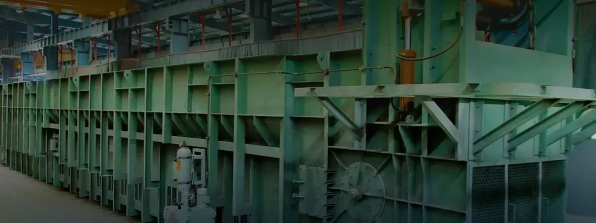
Case Study – Bottom ash (SSCC) & Fly ash (Dense Phase) Handling system for PF Boiler
Case Study – Bottom ash (SSCC) & Fly ash (Dense Phase) Handling system for PF Boiler
Bottom Ash Or Fly Ash Handling system for PF Boiler-
PROJECT SYNOPSIS
| Name of the Client / Purchaser | Jindal India Thermal Power Ltd., New Delhi |
| Location of the Plant / project | 2×600 MW TPP at Derang, Angul (Orissa) |
| Type of the Boiler / Make | PF fired / BHEL |
| Brief Scope of Work | Design, Engg., Manufacturing, Supply, Erection, Testing & Commissioning of complete Ash Disposal System |
Type of System
| Primary System | Bed Ash Handling System | Bottom Ash Hopperwith Hydraulic gates, Submerged Scrapper Chain Conveyor – 1 W+1Sb (Cap: 53TPH) with Clinker Grinder, Series of belt Conveyors upto BA Silo. Bottom Ash Silo Unloading System with vibratory feeder and chute for disposal through trucks |
| Primary System | Fly Ash Handling System | Positive Pressure type (Dense Phase) Pneumatic Conveying system, using Oil Injected Screw Type conveying air compressors. |
| Primary System | Silo Unloading System | |
| Secondary System | High Concentration Slurry Disposal System (Fly Ash) | Unloading FA through Screw feeder & Ash Mixer to Agitator Retention Tank followed by plate valve & charge pump and HCSD pump. Pumping Distance : approx. 2500 mtrs. |
Bottom Ash Or Fly Ash Handling system for PF Boiler-
BOTTOM ASH HANDLING SYSTEM:
Macawber Beekay successfully installed Submerged Scrapper Chain Conveyor (SSCC) system, followed by a combination of Belt conveyors system to handle semi-wet Bottom Ash from Boiler furnace to Bottom Ash Silos, equipped with truck Unloading system below the silo.
Furnace ash is discharged on a continuous basis into SCC of each unit, via a refractory lined steel construction bottom ash hopper installed below furnace. The furnace seal plate supplied by others dips into the seal trough filled with water around top periphery of bottom ash hopper for the sealing of furnace. The necessary clearance is provided between seal plate and seal trough bottom to take care of expansion of furnace.
Bottom Ash Hopper is provided with 4 (four) ash outlets, each having respective hydraulically operated discharge gates. These discharge gates are operated through a common hydraulic power pack. A dip box is provided below each hydraulic discharge gate and bottom portion of the dip box is dipped into the water filled in the top trough of the SCC in order to have a gas seal at all times of plant operation.
Spray nozzles are provided in the bottom ash hopper for quenching of ash and seal trough flushing pipe and cleaning of inspection window.
Economizer ash also flows into respective SSCC in slurry form for disposal.
Suitable LP water pumps are provided to meet the system requirement.
Structural Steel platforms have been provided to gain access to the hopper rodding points (poke holes) and observation windows.
PRINCIPLE OF OPERATION:
Hot Ash/Clinkers fall from furnace through bottom ash hopper into the horizontal trough (slag bath) of the SSCC from where it is continuously dragged away by scraper bars connected to two endless alloy steelround link chains and discharge the same into the clinker crusher through chute and onto the bottom ash belt conveyor for further disposal to bottom ash silo. Temperature and level of the water in the slag bath is maintained by continuous circulation of water supply. The trough water overflows through parallel plates to restrict ash particles within the trough itself and is collected in an RCC tank. This contaminated water from RCC Tank could be re-cycled back into the trough through heat exchanger and clarifier.
The bottom ash shall be directly disposed to open Truck from silos through discharge gate and vibratory feeder.
FLY ASH HANDLING SYSTEM:
System consisting of Dense Phase Pneumatic Conveying System.
Fly Ash from APH and ESP hoppers shall be conveyed through Dense Phase Pneumatic Conveying System to Fly Ash Silos
Brief write-up for System at APH:
There are 4 Nos. of outlet points for APH. The Ash Vessels below each APH hopper are clubbed together in series (Master + Slave) through a common conveying line. The fly ash shall be transferred to the FA Silo through a terminal box provided on its top.
Brief write-up for System at ESP:
There are nine fields in ESP with four passes. Each pass shall have 36 Hoppers.
Beneath each ESP hopper, an Ash Vessel system has been provided. Total 6 sets of fly ash conveying pipes have been provided for handling ESP ash for each boiler.
Each Ash Vessel is equipped with unique DOME VALVE at inlet along with necessary instrumentation.
System at Fly Ash Silo:
Total of 4 sets of fly ash silos have been provided for collection of fly ash from two boilers.
At top of each silo, 1 No. Vent Filter (reverse pulse jet type) is provided on top of FA Silo to vent out clean air to atmosphere. 1 No. Level probe for high level indication and 1 No. continuous level indicator is provided in FA Silo. Silos are equipped with Pressure relief valve and Manhole at silo top.
At conical portion of fly ash silos, Fluidizing pads have been provided.3 Nos. (2W+1S) Roots Blower and 3 Nos. heaters are provided for fluidization of set of two fly ash silos.
Conveying air requirement for both the units is met from a common bank of CA compressors. Separate Instrument Air compressors have also been provided dedicated to fly ash handling system.
System for Silo 1 & 2 : The FA Silo 1 & Silo 2 shall have three outlet points. First and second outlet point shall be provided with fly ash unloading spouts for unloading of fly ash into closed tankers and also ash conditioners for moist fly ash disposal into open trucks. The third outlet is provided with just isolation valve for any emergency unloading of fly ash.
System for Silo 3 & 4: The FA Silo 3 & Silo 4 shall have four outlet points. The Fourth Outlets points are connected withHCSD system for disposal of fly ash in slurry form.
PRINCIPLE OF OPERATION (Dense Phase Pneumatic Conveying system):
The operation of the system is simple and completely automatic. System has dual operatability either through level probe material sensing or timerbased mode.
In timer based mode, the system shall convey material automatically in batches at preset programmable interval of time.
In level probe mode, level sensing probe provided in the hopper above conveying vessels or transfer vessel shall sense the presence of material in the hopper and initiate the conveying cycle. Dome valve shall open and allow the material to gravitate into the transfer vessel for a preset time & then close automatically. On closure of dome valve, its seal gets inflated and signals the conveying air injection into the transfer vessel. The vessel gets pressurized and material resistance help pressure build up and conveys the material through steel piping to the destination silo.
When conveying is complete, the pressure drops down and is sensed by the control system, the air supply to the system is stopped and the cycle is complete now. The system is ready for the next cycle.
The total system is made automatic by use of level probe in destination silo to control the transfer of material. Complete system is flexible enough and programmable and automatically operated through a PLC based central control panel.
BED MATERIALHANDLING SYSTEM (Dense Phase Pneumatic Conveying system):
Total of 2 sets (One for each boiler) of bed material conveying system is provided for two boilers.
Bed Material is fed into MS surge hopper (by Purchaser). The Surge Hopper is provided with two sets of conveying systems, each connected to an individual conveying pipeline for conveying bed material to the boiler bunker.
At top of each boiler bunker, Vent Filter (reverse pulse jet type) andcontinuous level monitoring is provided.
LIMESTONE CONVEYING SYSTEM:
Continuous conveying system is provided for limestone handling. Macawber Beekay’s this technology has the capability to convey a wider range of materials with variable particle sizes using lower positive air pressures. This form of conveying is ideal for long distanceconveying and handling materials which are difficult to handle.
Total of 2 sets (One for each boiler) of limestone conveying system is provided for two boilers.
Crushed limestone from crusher house is collected in Product Hoppers below which conveying vessels are provided for conveying limestone to boiler bunkers.
System at Limestone Bunkers:
At top of each boiler bunker, Vent Filter (reverse pulse jet type) and continuous level monitoring is provided.
Dedicated conveying air compressors have been provided to for limestone conveying system, the other auxiliaries – common to ash handling system are retained.

